Printed Circuit Board
Following on from last time, my partner and I got excited about converting our breadboard project into a PCB.
We started out by drawing it on a whiteboard, but ultimately the design didn’t look much like that diagram at all. It was useful to draw though, as it became a good reference for us to glance up at to sanity check bits.
The first job was finding the right software to build a “Gerber” file, a file type which offers a many layered design of your circuit in realspace. After digging around for a while, we found EasyEDA, which worked directly with the PCB printer. In that, it gives you standard components that you can drag and drop onto the “board”, and then connect them all up.
You have total control over everything on the board, including where the tracks lie.
Printing the PCB ranged massively in cost depending on country: the UK was incredibly expensive. I was initially fine with paying above average for it to be built in the UK. However, for five boards we were looking at around £70. I could stomach this, if I had to. But compared to the USA, which was quoting around £20, it seemed crazy to pay so much. Since we weren’t considering the UK any more, we decided to look at a Chinese company who printed and shipped our five prototype boards to us for less than £9. In total.
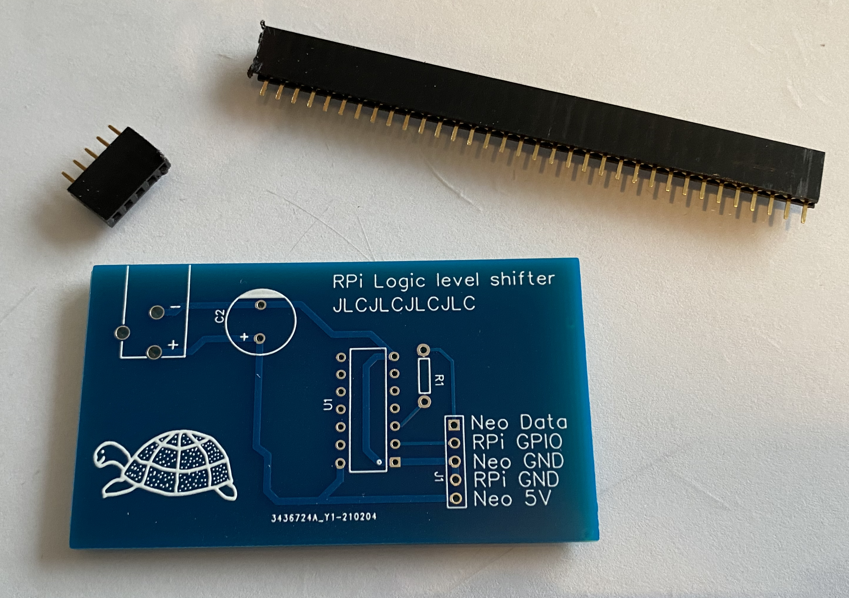
You’ll notice in the image above that there’s no components! Asking the PCB printer to add components drastically adds to the cost - if they’re adding one or one hundred components it still comes with a large price jump. As well as that, the level shifter we need wasn’t part of their catalogue of available items (so we’d have to send them in to them), so we decided to salvage the bits from the breadboard and solder them in ourselves.
We were delighted to see it working. It’s much cleaner than the breadboard. (Although, my photography and dusting skills could do with some improvement.)
![]()
Some changes we’d like to make:
- Clean up a few of the trace lines. I don’t mind this, but Tim thinks they’d be better straighter.
- Correct the “C2” label, which should just be “C1”.
- Even better, just write “capacitor” there.
- Reorder the IO/power labels so they make a bit more sense.
- Figure out why the “JLCJCL…” string is there there - that was just a placeholder the PCB printer was supposed to use for their internal tracking number, but instead they put that really small at the bottom.
I’d also like to take a look at making it as small as possible. I’m sure we can compress it better. Additionally, I’ll be buying a Pico to see if that works the same.
The next part of this project is figuring out how to make the Pi and the Neopixel share a power in, rather than needing the two. I’m sure that’s possible, right? They require different voltages, but stepping it down in a chip (much like the level shifter increases voltage) should be possible. The Neopixel power brick can certainly supply the amps.